Notes:
Level 1
LED:
Universal Symbols means symbols everyone knows
Positive = "+"
Negitive = "-"
Led diameter is 5mm
Led can only take 3 volts
Open and Close Circuits:
Open circuit: When there is a gap in the circuit
Closed circuit: when there is a complete loop
Insulators and Conductors:
Insulators: does not allow electricity to flow through it. E.X. rubber, wood, plastic, cloth, etc
conductors: Allows electricity to flow through it. E.X. Cooper, Metal, etc
Voltage and Current:
Voltage: power to your circuit
Current: how fast electricity flows in the circuit
Parallel = Voltage - Same, Current - Divides
Series = Voltage - Divides, Current - Same
Parallel and Series Circuits:
Series circuit: one loop
Parallel circuit: more than one loop
Fuse:
It will take in extra voltage and kill itself to protect the other components
Short Circuit:
A short circuit is a shortcut for electrons
It does not use electricity
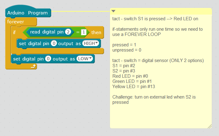
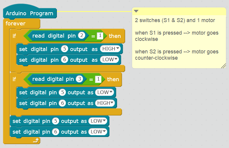
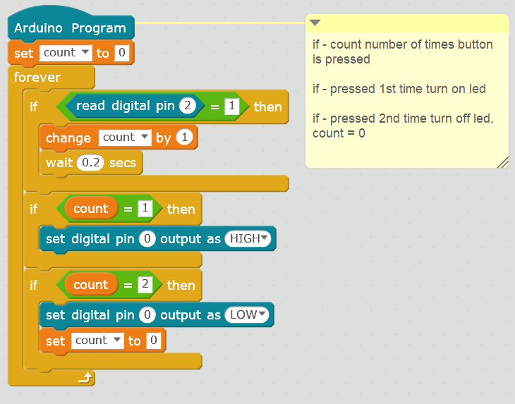
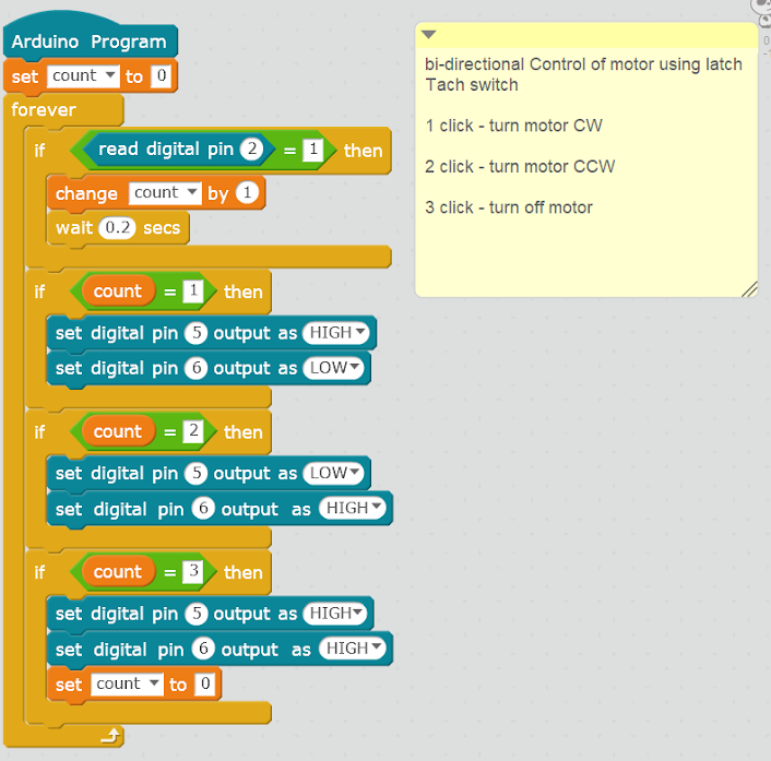
Switches:
2 families of Switches(momentary(tact switch), and Latch(slide switch))
Tact switch is single pole single throw (spst)
Slide switch is single pole double throw (spdt)
Switches do not use electricity
Buzzer:
Unidirectional: One-way p-p, n-n. E.X. LED, Buzzer
Bidirectional: two-way p-p, n-n or p-n, n-p. E.X. Tact switch, motor
Monophonic: 1 sound
polyphonic: More than 1 sound
Stereophonic: base and treble
Buzzer is Monophonic
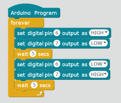
Motor:
'''
Specs:
Speed = 3600 rpm
RPM = Rotations Per Minute
Direct current - dc gearless motors
'''
DC - Direct current
AC - Alternating (changing) current
Canada = 110 - 120 AC V
Adapter (Laptop charger) - changes AC to DC
Rectifier - changes DC to AC
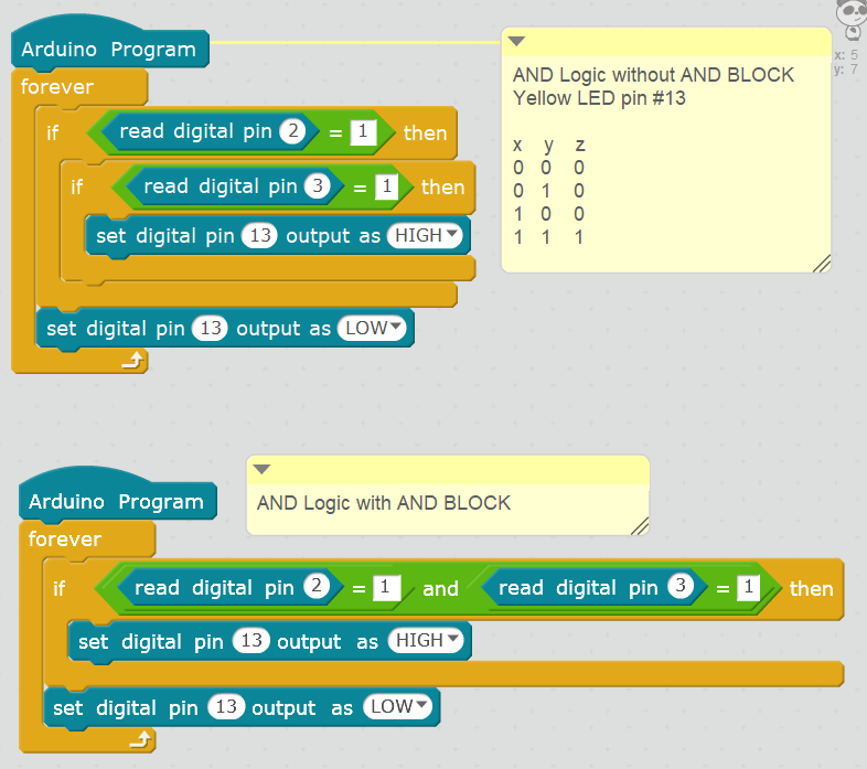
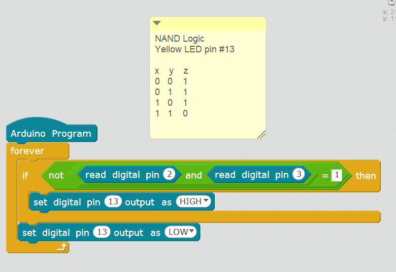
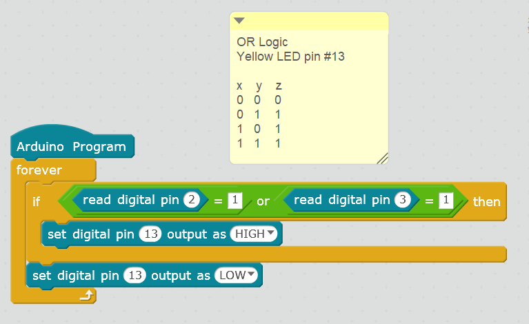
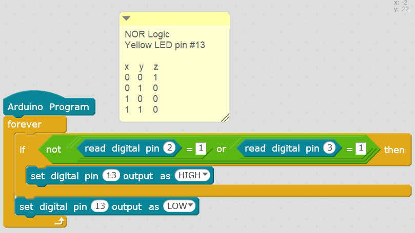
Logic Gates:
Binary = 1(on), 0(off)
NOT Logic Gate:
| x | y |
|---|---|
| 0 | 1 |
| 1 | 0 |
OR logic Gate:
| x | y | z |
|---|---|---|
| 0 | 0 | 0 |
| 1 | 0 | 1 |
| 0 | 1 | 1 |
| 1 | 1 | 1 |
AND Logic Gate:
| x | y | z |
|---|---|---|
| 0 | 0 | 0 |
| 1 | 0 | 0 |
| 0 | 1 | 0 |
| 1 | 1 | 1 |
NAND Logic Gate:
| x | y | z |
|---|---|---|
| 0 | 0 | 1 |
| 1 | 0 | 1 |
| 0 | 1 | 1 |
| 1 | 1 | 0 |
NOR Logic Gate:
| x | y | z |
|---|---|---|
| 0 | 0 | 1 |
| 1 | 0 | 0 |
| 0 | 1 | 0 |
| 1 | 1 | 0 |
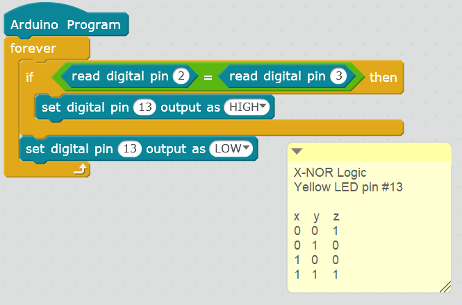
XNOR Logic Gate:
| x | y | z |
|---|---|---|
| 0 | 0 | 1 |
| 1 | 0 | 0 |
| 0 | 1 | 0 |
| 1 | 1 | 1 |
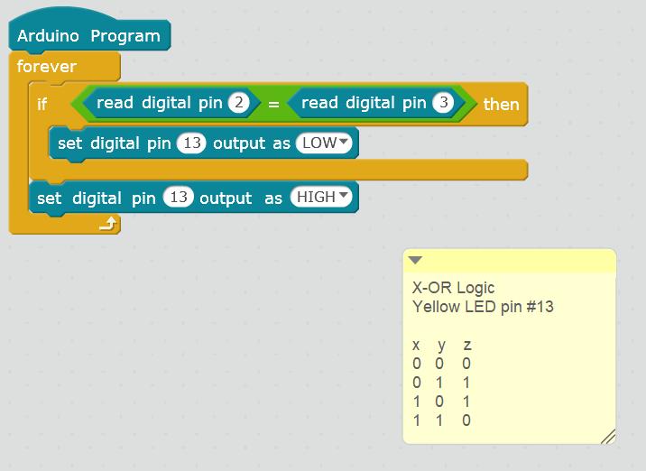
XOR Logic Gate:
| x | y | z |
|---|---|---|
| 0 | 0 | 0 |
| 1 | 0 | 1 |
| 0 | 1 | 1 |
| 1 | 1 | 0 |
Resistors:
Resistor: Slows/Blocks the flow of current
Bidirectional
Voltage - volts (v)
Current - Amperes (amps)
Resistance - Ohms(Ohms)
LDR:
LDR = Light Dependent Resistor (photoresistor)
Bidirectional
Light = LED bright
No light = LED dim
Trim Pot:
Potentiometer: Variable Resistor
Generator:
Battery - Has stoblue energy
Generator - Creates new energy
Practice Kahoot:
Click here for Kahoot!
Level 2
Controller:
CH 1- Latch Push Button (SPST)
CH 2- (not used in this level)
CH 3 and 4 - Rocker Momentary Switch(DPDT)
CH 5 and 6 - Latch Switch(DPDT)
Motors:
Level 1 - Gearless Motors
Level 2 - Geared Motors
Bigger the gearbox the slower the speed
Area of a Rectangle:
A = L × W
A = L × W = 15 Cm × 5 Cm = 752
2 = Cm × Cm
3 = Cm × Cm × Cm or Volume
Radius and Diameter:
Radius: Distance from the center of the circle to the edge of the circle
Diameter: distance deom the edge of the circle to the other edge
Perimeter and Circumference:
Perimeter: The total length of the outer edges of the shape
Perimeter = side 1 + side 2 + side 3 + side 4
Circumferece: The length of the outline of the circle
Circumference = 2πR = 2 × pi(π) × r
pi (π) = 3.14159265358979323
Area of a circle:
A = πr2 = 3.14 × r × r
Volume:
Volume: The space inside a 3D object
V = A × H
Rectangle:
A = L × W
V = A × H
Cylinder:
Area of a circle:
A = πR2
Volume of cylinder:
V = A × H = πR2 × H
Mass and Weight:
Earth - Gravity = 9.8 m/s2
Moon - Gravity = 1.62 m/s2
Mass = 50 KG
Weight = Mass x Gravity
Earth weight = 50 Kg x 9.8m/s2 = 490 N
Moon weight = 50 Kg x 1.62m/s2 = 81 N
N = Kg.m ÷ S2
Density:
Density: A measurement that compares the amount of matter in an object
Density = P
Mass = M
P = M ÷ V
M = P × V
Volume = M ÷ P
Speed:
Speed: "a rate at which something moves"(How fast something moves)
Speed = Distance(meters) ÷ Time(seconds)
Force and Torque:
Force: It is a pull or push motion(Force can make things move, change an items speed and an objects shape)
Linear direction (straight)
Unit for Force: Newtons(N)
Torque: torque is a force applied in a rotational movement
Unit for Torque: Newton-Meters(N-M)
Force = torque ÷ Radius
Relationships between Torque and Speed
- Torque is inversely proportional to Speed
- When torque increases, speed decreases
Torque = 1 ÷ speed
Torque go up, Speed go down
Newton's Law of Motion:
Newton has 3 laws of motion:
#1 - Inertia: An object at rest will remain at rest and an object in motion will remain in motion unless both situations are acted upon with an external force
#2 - F = Mass × Acceleration: Force is equal to mass times the speed of an object
#3 - Action and Reaction: Every action has an equal and opposite reaction
Level 3
Solar Energy:
Basic Facts About Solar Power:
- Alternate power source (different power other than battery
- Renewable energy (Energy from nature and can be used over and over again)
- "Comes from the sun" (Taking energy from the sun/light source)
- Takes energy from the panels generated during daytime and uses the stored energy at nighttime (The energy is stored in a battery)
Solar Panel provided in kit provides:
6V - voltage provided
0.25Amps - current provided
Solar Cells vs Solar Panels:
- Multiple solar cells are used to create solar panels
- Multiple solar panels are used to create solar arrays
to Increase the Efficiency of a Solar Panel:
- Black Colour Coating - Absorbs heat/light
- Solar Tracking System - Moves solar panel to face the sun
- Lenses - Collect the light beams
Equation
Power (P) = Voltage (V) × Current(I) = 6V × 0.25A = 1.5 Watts
Signals:
- Information in forms of electrical waves
- Devices that send/transmit signals are called transmitters
- Devices that get/receive signals are called receivers
2 types of signals:
- Analog - More than 2 states (0V - 5V)
- Digitals - only 2 states (on/off, high/low, 1/0)
Wireless:
- After creating the data signal needed, we have to send it from one place to another
- Transferring the data from one place to another place is called communication
Source (Transmitter) --> Channel --> Destination (Receiver)
Source:
- Data signals such as analog/digital signals are generated here
Channels:
- The connection between the "source" and "destination"
- For wired communication, wires act as a channel which connects the source to the destination
- In wireless communication, there are no wires connection between the source and the destination//
- The "air" acts as a channel which connects them
Destination:
- The person/user that the message(data) was created in the source for
Transmitter and Receiver:
Transmitter:
#1 Information/data from the 4-bit data Switches (tact switch) are transmitted to the IC (Integrated circuit).
#2 From the 8-bit BIP (Dual In-Line Package) Switches, the address for the destination is sent to the IC.
#3 The information/data and the address is transmitted to the encoder which outputs it as electrical waves
Receiver:
#1 The address is verified by the DIP (Dual In-Line Package)
#2 The information/data sent as an electrical wave from the transmitter is sent to the IC (Integrated Circuit)
Dual In-Line Package (DIP Switches:
- Dual means 2 options/states -> On/Off
- 28 = 256 address options -> 2 × 2 × 2 × 2 × 2 × 2 × 2 × 2
Exponents:
- 23 = 2 × 2 × 2 = 8
- 44 = 4 × 4 × 4 × 4 = 256
- 35 = 3 × 3 × 3 × 3 × 3 = 243
- 21 = 2
- 20 = 1
- 70 = 1
Leds on Receiver:
5 leds on the receiver -> D1, D2, D3, D4, VT
VT:
VT - Valid Transmission
VT lets the user know that there is data incoming from the transmitter
Integrated Circuit (IC):
- Multiplexer (Mux): Amplifies current
- transmitter: 1 IC
- receiver: 3 IC
- Motor Driver: Additional 1 IC -> Used to make sure there is enough current sent to the motor
- Encoder is used to convert your information to electrical waves
- Analog -> Encoder (Transmitter) -> electrical waves -> Encoder (Reciever) -> Digital signal
-Frequency: The number of times something happens during a certain time period.
Unit of Frequency: Hertz (Hz)
F = 1 ÷ time (Inversely proportional (Opposite))
- Free to use (Non-License) frequency is 434 KHz
- 5V -> VCC
- 0V -> GND (Ground)
Level 4 Notes
RAM and Rom:
RAM: Random Access Memory (temporary)
ROM: Read Only Memory (permanent)
Uniko Ekam Board:
ATMega328
32kb of ROM
28 pins
8-bit micro controller
2 kb of RAM
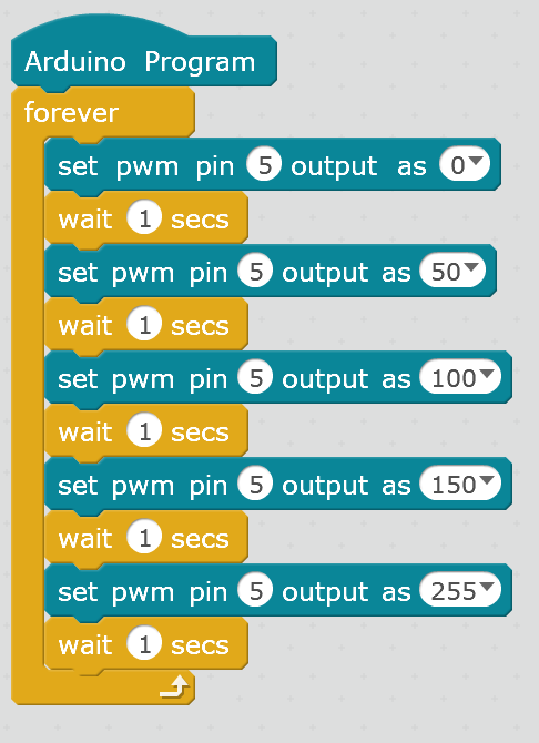
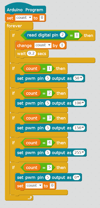
6 PWM pins (~3, ~5, ~6, ~9, ~10, ~11)
Oscillators: clocks for pulse (silver thing beside IC)
Internal oscillator -> 8 MHz freq
External oscillator -> 16 MHz freq
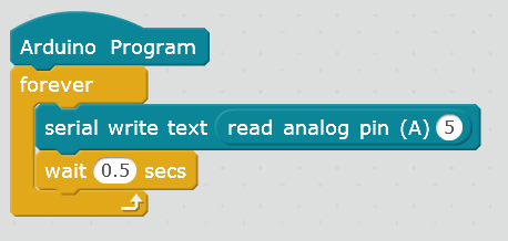
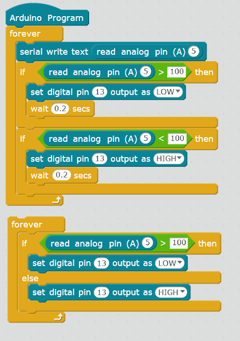
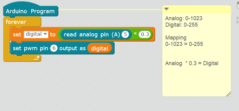
Analog and Digital Inputs and Outputs:
Analog Inputs -> 0 - 1023 or 1 - 1024
Digital outputs -> 0 - 255 or 1 - 256
Computer Storage Unit Conversions:
8 Bits - 1 Byte
1024 Bytes - 1 Kilobyte
1024 Kb - 1 Megabyte
1024 Mb - 1 Gigabyte
IR Remote:
TSOP 1738 - IR Remote
TSOP stands for "Thin Small Outline Package"
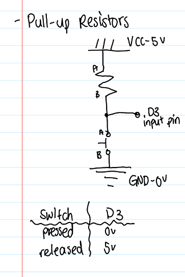
Pull-Up Resistors:
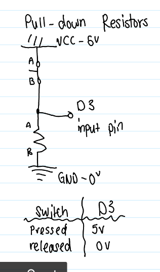
Pull-Down Resistors:
Level 4 Codes


Level 5 Notes
Binary To Hexadecimal:
First break all the numbers into groups of 4 starting from the back
010111001011 = 0101, 1100, 1011
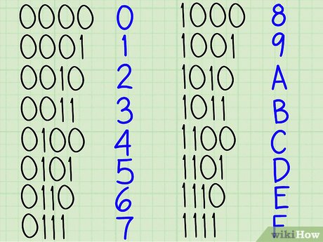
Match the corresponding numbers to letters/numbers
0101 = 5
1100 = C
1011 = B
010111001011 = 5CB
Uniko DVI:
IC(Integrated Circuit) -> ATMega32A
Board has 40 Pins, 4 ports(A,B,C,D)
Port A:
Pins #A 0-A 7 -> altogether
Port B:
Pins B 0 and B 1 -> Ultrasonic Sensor
Pin B 2 -> TSOP
Pin B 3 -> Servo Motor
Pins B 4 - B 7 -> altogether
Port C:
PC 0 - PC 2 and PC 4 to PC 7 -> LCD display
PC 3 -> Buzzer
Port D:
D 0 - D 3 -> altogether
D 4 and D 5 -> Motor Driver 1
D 6 and D 7 -> Motor Driver 2
Registers:
DDR(x) Register:
DDR - Data Direction Register
DDR sets the direction as input and output of the PORT
input - 0b00000000 (0 - input)
output - 0b11111111 (1 - output)
input -> accepting signals/data from the outside
output-> give signals/data from outside
PORT(x) Resister:
-> Sets the pins of a port as HIGH (1) or LOW (0)
-> Value of the pins can be set ONLY when the PORT is set as an output using DDRx register
1. DDRC=0xFF -> entire port as output
2. PORTC=0xFF -> all pins in PORT C as high
Pin(x) Register:
-> used to read the data coming from the port
-> In order to read the data, the PORT needs to be set to input using DDR(x) register
1. DDRC=0x00 -> PORT C all input
2. PINC
Level 5 Codes
After using code use command 'CTRL+T' to format the code
// Embedded C
#include<avr/io.h>
#include<util/delay.h>
int main (void) // Main Program
{
// WRITE CODE HERE //
while(1) // Forever Loop
{
// WRITE CODE HERE //
} // End of While Loop
} //End of Main Program
//library
#include<avr/io.h>
#include<util/delay.h>
int main (void) //main program
{
DDRD = 0b11111111; //entire port D is output
while(1) //While True True/False 1/0
{
PORTD = 0b00000001; //pin D0 - Red is HIGH
_delay_ms(1000); //delay for 1 sec
PORTD = 0b00000000; //pin D0 - Red is LOW
_delay_ms(1000); //delay for 1 sec
}
}
//library
#include<avr/io.h>
#include<util/delay.h>
int main (void) //main program
{
DDRD = 0b11111111; //entire port D is output
DDRB = 0b11111111; //entire port B is output
while(1) //While True True/False 1/0
{
PORTD = 0b00000001; //pin D0 - Red is HIGH
PORTB = 0b00000000;
_delay_ms(1000);
PORTD = 0b00000010; //pin D1 - Green is HIGH
PORTB = 0b00000000;
_delay_ms(1000);
PORTD = 0b00000000;
PORTB = 0b00010000; //pin B4 - Blue is HIGH
_delay_ms(1000);
}
}